4.0.1 What is a multisine EIS signal?
One of the criticisms of EIS is the prolonged testing time when measuring low frequencies. These measurements can take hours depending on the requested frequency range and point density. The duration of the measurement also raises issues with stability as the system may drift from its steady state due to internal or environmental factors. The use of multisine signals can help combat these problems by sampling multiple frequencies at once to provide quicker EIS measurements.
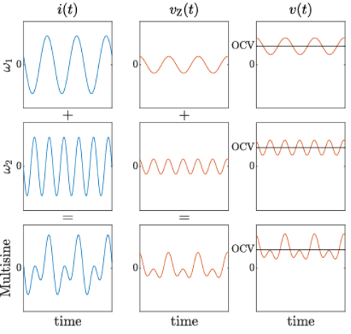
Multisine EIS operates by measuring impedance at various frequencies simultaneously. This can drastically decrease overall measurement time as low frequencies are sampled in parallel. In multisine EIS, many frequencies are superimposed upon one another with each individual sinusoid having the same amplitude but differing phases [14]. The figure below depicts the resulting multisine signal as individual sine waves at different frequencies are summed. Although applying many frequencies at once can make measurements much faster, the resulting peak amplitude of the multisine wave must be considered. The signal’s peak amplitude is affected by constructive interference between the frequencies leading to large spikes that may induce a non-linear response in the electrochemical system. Fortunately, the constructive interference between frequencies can be minimized by adjusting key experiment parameters.
4.0.2 Crest factor optimization
Although multisine EIS can be significantly faster than single sine EIS, there is a trade-off due to the constructive interference in the multiple signals. Since single sine measurements measure each frequency independently, they do not possess such a limitation and as a result can achieve a greater signal-to-noise ratio. By shifting the phases of individual frequencies in the multisine signal, it is possible to minimize the amount of constructive interference. Phase shifting reduces the limitation on the max amplitude of each individual frequency within the multisine signal, thus allowing for a greater signal-to-noise ratio.
To maximize the signal-to-noise ratio and minimize the constructive interference of the multisine signal, crest factor optimization is employed. The crest factor refers to the ratio between the height of the peaks in the multisine signal in comparison to the average amplitude. The phases of the superimposed EIS signals are selected to minimize the crest factor. This can be done by assigning random phases from a uniform distribution or using more sophisticated mathematical algorithms. Shroeder’s optimization algorithm is one of the most popular methods for logarithmic spaced frequencies as it focuses on phase positioning to promote destructive interference using the frequencies’ harmonics.
4.0.3 Converting time domain to the frequency domain
Synthesizing multisine EIS data is more complex relative to single sine EIS due to the presence of multiple frequencies being sampled at once. To deconstruct this complex waveform, a fast Fourier transform (FFT) is applied to convert the data from the time domain into the frequency domain. The FFT is a mathematical algorithm that breaks down the multisine wave into its individual frequency components. The FFT is foundational for periodic data analysis in many different fields from electrical engineering to audio and image processing. With the voltage and current data from the individual frequencies, the impedance is calculated as the ratio between the voltage and current spectra using Ohm’s law.
Want to learn more? Speak with us today!
